Walkthrough for GUI-based template matching
Contents
Template matching
In this technique, a template representing a molecule of interest is systematically cross-correlated against a tomogram, producing a cross-correlation map of the tomogram. Each pixel in this map represents a score assigned the corresponding pixel in the tomogram map. This score measures the similarity of the neighbourhood of the tomogram pixel to the used template. This similarity is measured exclusively inside a mask.
Model-aware template matching is meant as an extension of the normal template matching algorithm in Dynamo. The main change introduced in model-aware template matching is that the tomogram is split in chunks that are meant to be meaningful from the point of view of the tomogram models. This allows for the reduction of needed computation by restricting the angular combinations of the template to be scanned.
In this walkthrough, the methods to manually manipulate these chunk is introduced.
Walkthroughs on basic TM in Dynamo and model-aware TM are also available.
Data set
Getting the data
Currently the data necessary to tun this walkthrough can be downloaded using the link:
https://saco.csic.es/s/SmymKiHxswSoyoP
It consists in: a tomogram fullReconstructionWBPCTFDW.mrc, a template templateMCP.mrc, a mask maskMCP.mrc and a fourier mask fmaskMCP.mrc.
Tomogram description
The tomogram contains Bdellovibrio bacteriovorus acquired by fast-incremental method. The tomogram has been generated using the tilt series from EMPIAR dataset entry 10226. The pixel size is 2.743 Å. The tomogram has been generated around an area of the bacteria presenting methyl-accepting chemotaxis protein (MCP) arrays. The template an average of MCP array.
Acknowledgements
The tomogram has been generated using the tilt series from EMPIAR dataset entry 10226 described in the paper "Chreifi, G., Chen, S., Metskas, L. A., Kaplan, M., & Jensen, G. J. (2019b). Rapid tilt-series acquisition for electron cryotomography. Journal of Structural Biology, 205(2), 163–169. https://doi.org/10.1016/j.jsb.2018.12.008". The alignment and reconstruction was done using the Dynamo AWF procedure as detailed in "Coray, R., Navarro, P., Scaramuzza, S., Stahlberg, H., & Castaño-Díez, D. (2024). Automated fiducial-based alignment of cryo-electron tomography tilt series in Dynamo. Structure, 32(10), 1808-1819.e4. https://doi.org/10.1016/j.str.2024.07.003". The template has been generated by STA as described in the same paper.
Visualizing the tomogram
The tomogram can be found in the path with:
tomofile = 'fullReconstructionWBPCTFDW.mrc';
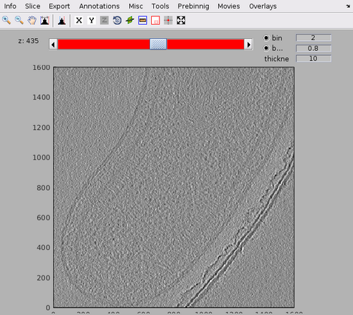
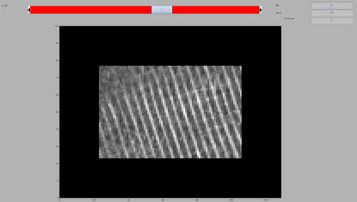
We can get a first glance on how the tomogram looks like:
dshow(tomofile);
The tomogram should appear like the following figure. Note the MCP arrays on the inner membrane of the bacteria.
Estimation of the missing wedge
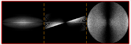
We can quickly check the extent of the missing wedge in the tomogram. We extract a sample of the tomogram:
fragment = dynamo_read_subtomogram(tomofile, 'r',128,'c',[450,450,450]);
and plot a map of the distribution of the Fourier coefficients:
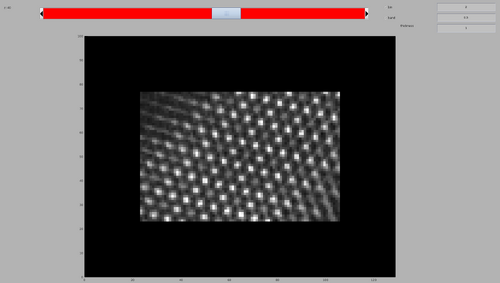
dynamo_wedge_estimate(fragment,'show',1);
The wedge estimation will show a bi-directional tilt-series acquisition by fast-incremental from around -60 to 60 degrees.
Inspecting the template and mask
In this walkthrough, a template and its mask are already provided. The template was generated by averaging ~50000 particles aligned with Dynamo.
The template can be loaded by:
av = dread('templateMCP.mrc');
And the mask can be loaded by:
mask = dread('maskMCP.mrc');
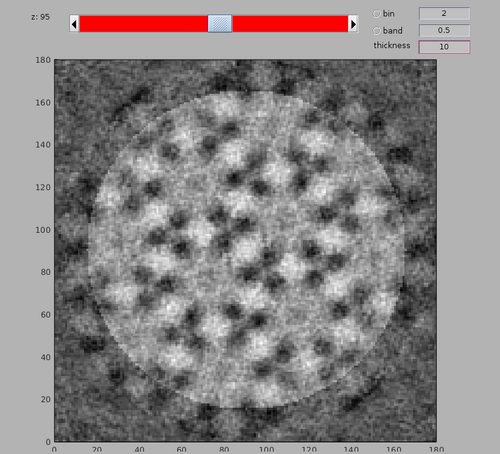
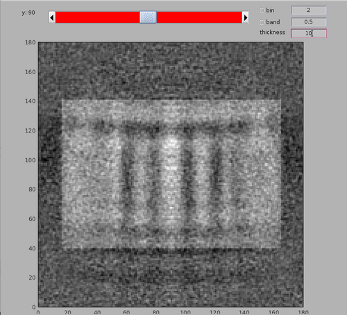
The template and mask positioning can be inspected with:
dshow(av+mask);
Note the membrane bilayer on which the MCP array is present is at the bottom of the template. The bacterial cytoplasm would be at the top of the template.
Description of basic chunk manipulations
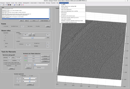
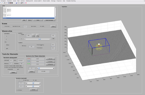
The GUI for chunk manipulation is dtmslice with a tomogram as input. It has a tab called Template Matching in the top bar of the GUI. It is through this tab that general attributes of chunks distributions and TM processes can be manipulated. Additionally, each chunk has its own attributes (such as position and size) that can be manipulated after they are created.
Chunk creation
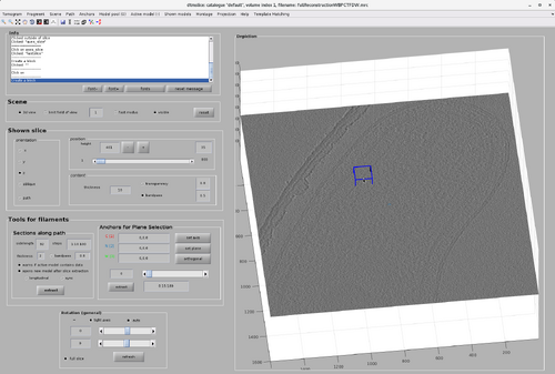
Create a chunk by pointing the cursor on the tomogram and pressing the "B" key.
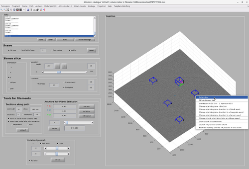
Multiple chunks can be created by pressing the "B" key again. A chunk can be deleted by right-clicking it and selecting "Delete box". This will also update the number of existing chunks noted in the Template Matching tab.
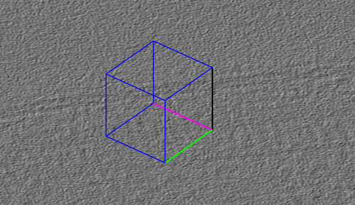
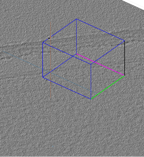
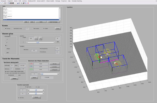
Each created chunk is represented with a colored box indicating its position, size and orientation in the tomogram. The coordinate system defined by each chunk is noted by the colored axis. The X axis is magenta, the Y axis is green and the Z axis is black.
Basic chunk manipulations
Resize a chunk by clicking an edge and dragging it with the cursor. The figure shows the chunk being increased in size along all directions.
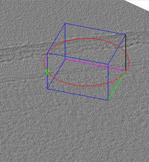
Move a chunk by shift-clicking an edge and dragging it with the cursor. The figure shows the chunk being moved along its Z direction.
Rotate a chunk by alt-clicking an edge and dragging it with the cursor.
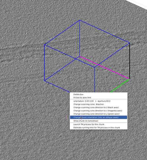
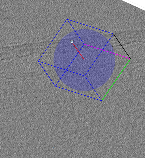
This can also be done by right-clicking the chunk and then selection the option "Change chunk orientation (into an oblique view)". This will spawn a interactable lever that can rotate the chunk in any direction.
Chunk inspection
The tomogram data included in a chunk can be inspected by right-clicking the chunk and selecting "show chunk (in tomoshow)".
The data can also be inspected through a chunk-specific template match process that will be described in the following sections
Chunk cone setting
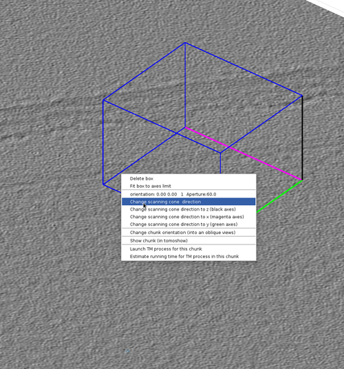
The chunk cone orientation is the direction around which a template would be oriented during template match. It can be seen as the most probable direction that copies of the template present in the volume defined by the chunk. The graphical object allowing changes in the cone orientation is accessible by right-clicking a chunk as in the next figure.
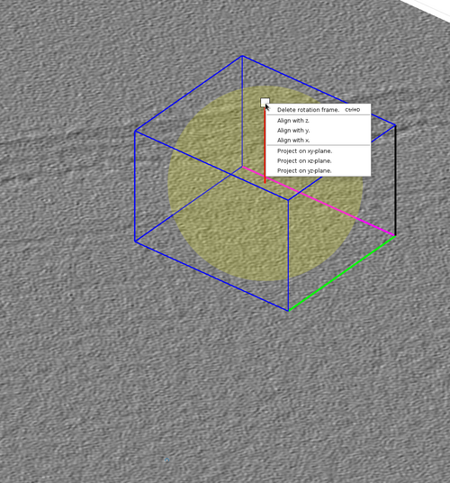
The graphical object has some functionalities that can be accessed by right-clicking it as in the next figure.
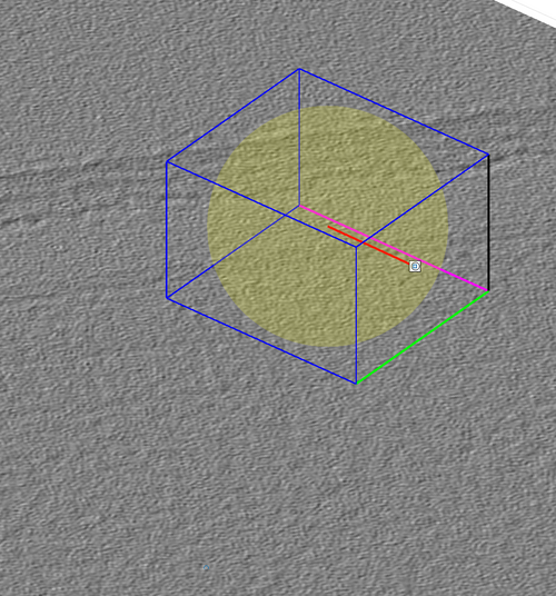
The cone orientation is changed by dragging the lever as in the following figure. Once the cone orientation is satisfactory, the lever graphical object should be removed by pressing the "Delete rotation frame" option shown in the previous figure.
Per-chunk TM
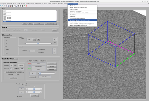
As mentioned before, it is possible to run a TM project on a chunk directly from the GUI. This can be done by right-click the chunk and select "Launch TM process for this chunk". However, more parameters are necessary than only the chunk positions, size, orientation and cone orientation. These parameter can be accessed by selecting the "Template Matching" option on the top bar of the GUI and clicking "Settings for template match process" as in the next figure.
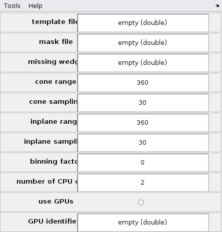
The TM parameter GUI is initially blank and need to be filled to be able to run a per-chunk TM. The main advantage of per-chunk TM is that it can be done directly from the GUI and on any type of chunk, including oblique chunks.
It should be noted that the area of the chunk that will generate valid cross-correlation scores is reduced by half of the size of the template in all directions.
Relationship between GUI models and tessellations
The GUI allows the creation and manipulation of tessellation with the tool mentioned in the previous section. However, these tessellations will be saved or loaded from .omd files. This can be done from the "Template Matching" tab in the GUI with the options "Save chunk distribution" and "Load chunk distribution from .omd file".
However, TM processes require a tessellation in either table or dStar format as described in the tutorial on model-aware template matching. This difference in format exists because .omd file tessellations are simplified so that their representations in the GUI would not be cumbersome. As such two converting functions are available in the Dynamo TM package:
The function dpktomo.match.modelling.createTesselationFromGUIomd converts an .omd tessellation into a dStar tessellation ready for dynamo_match.
The function dpktomo.match.modelling.saveTesselationAsGUIomd converts a dStar tessellation into an object that can be saved as a .omd file with dwrite.
Walkthrough on chunk manipulation
In this walkthrough the basic function described before will be used to create a tesselation and run a model-aware TM project. Additionally, on per-chunk TM will be tested with different cones.
Chunk setup
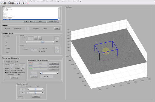
First, if not done already, open the dtmslice GUI with the tomogram.
dtmslice('fullReconstructionWBPCTFDW.mrc');
Then, create a single chunk in the top area of the bacteria presenting an MCP array. For now, do not use oblique chunks.
Ensure the chunk is thick enough to include the MCP array area even considering the template size.
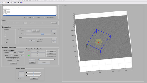
Rescale and shift the chunk until a configuration similar to the following figure is reached. The cone orientation will be left as the default one for now (that is, collinear to the Z axis of the tomogram).
Global TM
In this first experiment, an per-chunk TM with isotropic angular scanning will be used.
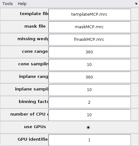
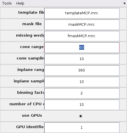
Howver, first it is necessary to set up the global TM parameters from the GUI. Update the GUI as in the following figure.
This setup will allow the GUI to access template, mask and missing wedge mask. The scanning ranges are 360 degrees to ensure isotropic angular scans. The angular scanning steps are set to 10 to allow fine enough sampling to achieve good cross-correlation maps. The binning is set to 2 to speed up calculations.
It is preferable to compute using GPUs for computing speed. Only one GPU is required. If more than one GPU are accessible by MATLAB, their corresponding id numbers can be checked with the MATLAB command:
gpuDeviceTable
The per-chunk TM can then by launched. Right-click the chunk and select "Launch TM process for this chunk". This will automatically create a folder called "chunkTM.CTM" containing the oblique chunk and its resulting TM process.
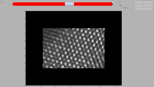
Finally, inspect the resulting cross-correlation map. In the created folder this can be done by:
dshow('process.TM/cc.mrc')
Cone-restricted TM
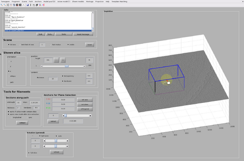
One of the main advantages of tesselation is that each chunk can limit the number of scanning angles by exploiting the know general orientation of the particle of interest present in the chunk area. This information is encoded in the cone orientation of each chunk. In this case, we know that the chunk is positioned on the top of the bacteria presenting the MCP arrays. This means that the MCP template is expected to identify the MCP array when it is oriented towards the bottom of the chunk. As such, updated the chunk orientation appropriately like in the following figure.
The general TM parameters must be updated as well. In particular the cone range should be reduced from 360 degrees to 60 degrees.
The per-chunk TM can then by launched and inspect the resulting cross-correlation map. In the created folder this can be done as before:
dshow('process.TM/cc.mrc')
The map will look similar to the previous per-chunk TM, but the computing time will be reduced by a factor of 10.
It must be noted that cone orientation can be used to test if sets of template orientations are not present. For example, we it is not expected that the MCP array on top of the bacteria will be horizontal. Update the chunk orientation like in the following figure.
The per-chunk TM can then by launched and inspect the resulting cross-correlation map. The cross-correlation map shows a lack of matches for the scanned orientations, as expected.
Walkthrough on tessellation generation
Tessellation are sets of chunks an cone orientations designed to be used by dynamo_match for advantageous TM. Here, the process to create and uses tesselations by GUI is shown.
Add more chunks
Firstly, add two new chunks with their cone orientations with the GUI as in the following figure. In total three non-oblique chunks are created.
Now, save the tesselation to disk by pressing the "Save chunk distribution" in the "Template Match" tab. This will create a file tesselation.omd to disk.
Generate a tesselation
As mentioned before, a .omd file need ot be converted to a star object to be an accepted input of dynamo_match.
The conversion can be done by:
star = dpktomo.match.modelling.createTesselationFromGUIomd('tesselation.omd');
The values encoded in the star object cen be inspected with:
star.tbl
The properties will look similar to the following:
    index     tdrot      tilt       narot      posX      posY      posZ     sizeX     sizeY     sizeZ     coneRange    inplaneRange
    _____    _______    _______    _______    ______    ______    ______    ______    ______    ______    _________    ____________

      1      -156.91    -160.25     156.91    702.55    743.66    564.27    515.44     397.2     270.9       60            360
      2       147.92    -97.808    -147.92    912.01    455.29    326.33    414.75    387.03    242.75       60            360
      3      -51.289    -78.113     51.289     486.3       883    322.65    455.65    549.42    282.14       60            360
Run model-aware TM with manual tessellation
Finally, a full model-aware TM process can be run.
pts_GPU = dynamo_match('fullReconstructionWBPCTFDW.mrc','templateMCP.mrc','mask','maskMCP.mrc',...
'outputFolder','MCP_tesselation',...
'ytilt',[-60,60],'is',10,'cs',10,'bin',2,'mw',10,'gpus',1,'tilingTable',star);
The resulting TM object pts_GPU can be then used as in the tutorials on basic TM and model-aware TM.
Additional functionalities
Two other functionalities will be introduced in this section. First, an per-chunk TM with an oblique chunk and then a conversion of dynamo_match tesselation into an .omd file ready to be loaded in the GUI.
Oblique chunks
Oblique chunks are currently not supported by dynamo_match. However, per-chunk TM can be done on oblique chunks. First, create an oblique chunk with appropriate cone orientation like in the following figure.
Per-chunk TM can then by run as in the previous sections.
Manipulation a tessellation with the GUI
The GUI can save and load .omd files, allowing of their manipulation and as such, the manipulations of tesselations.
If a tesselation is available as a star object, it can be converted in a .omd object with:
newomd = dpktomo.match.modelling.saveTesselationAsGUIomd(star);
Which can be save to disk as usual:
dwrite(newomd,'tesselation_back.omd');
The new .omd file can then be loaded by the GUI.
Note that tesselations can be generated automatically with the functions:
dpktomo.match.modelling.estimateTesselationForFilament
dpktomo.match.modelling.estimateTesselationForMembrane
dpktomo.match.modelling.estimateTesselationForDipole
and the creator of tesselation star objects:
dpktomo.match.modelling.setUpTilingTable
More information on this can be found in the tutorial on model-aware template matching.
Programmatic GUI customization for template matching
It is possible to add custom functionalities to the GUI as described in the corresponding tutorial.
