Basic detector workflow for Lacey grids
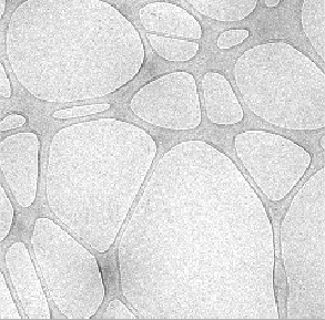
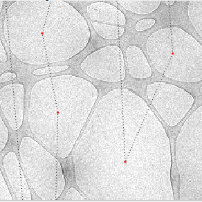
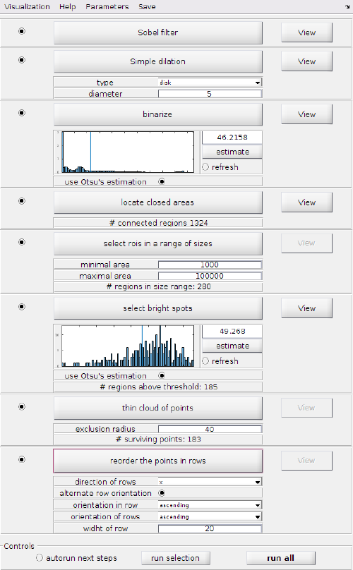
This is the default detection workflow for the Hole Picker, suitable for Lacey grids. Its execution GUI comprises 7 steps (detailed below), and it bases on the idea of using an edge detection approach to enhances the carbon/hole boundaries, so that each hole becomes a disconnected region in the image graph.
Contents
Algorithmic steps
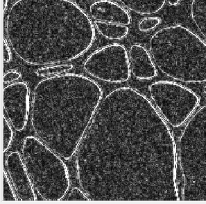
Sobel filtering
Produces and image that enhances the boundaries between holes and carbon.
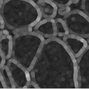
Boundary dilation
The goal of this step is twofold:
- strength the boundaries, to that holes become totally enclosed by high values (bright pixels in the sobel transform)
- eliminate the carbon space between holes.
Uses the dilation morphological operator to widen the found boundaries. The user can choose how many pixels to use in the dilation. Too large values will delete small holes, or might allow impurities inside a hole to grow and eliminate the hole altogether. On the other hand, too small values may generate boundaries that are not totally closed around a hole. This will prevent this hole from being detected in subsequent steps.
Binarization
Boundaries should be brighter than background. The goal of the step is to locate all pixels corresponding to the (dilated) boundary. Then, the step analyzed the remaining connected areas, considering each of these a different roi (region of interest).
Size based roi selection
The user marks maximum and minimum number of pixels expected in a roi. This step gets rid of small holes and also of big areas that correspond to the background.
Intensitiy based selection
This step is used to eliminate rois that correspond to inter hole carbon areas. The step counts the total intensity in each roi and divides it with the number of pixels, showing an histogram of this intensity density. Each bar is the number of rois whose intensity density falls inside a given bin. Carbon areas expected to have overall a darker color than grid holes and reside thus in the left area of the histogram.
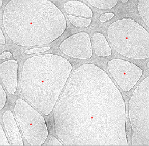
Thinning of selected points
The sets of points is thinned in order to match an user decided minimum density between holes.
Point reordering
The points are given a numbering and organized in rows. The user can choose the ordering: top to bottom or left to right, as well as the width of the bin that determines which points will be assigned to a given row.
Workflow GUI
The GUI allows for independent execution of each step. Alternatively, the user can just click on 'run all' (at the right bottom corner of the GUI) to execute all the steps at once. If any viewing GUI is opened, the result of each step will update automatically. When the last step it's computed, the results will be exported to the main Hole Picker GUI.
Support tools
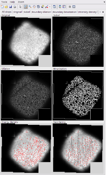
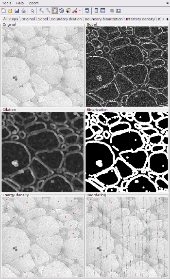
With the Visualization menu in the workflow GUI you can launch a view that represents the result of all the steps in the workflow, updating the results after each execution.
